Large-current LC Filter Using an Amorphous Magnetic SM Coil
- Types of low-pass filters
- Low-pass LC filter design
- Effects of parasitic components
- LC filter features and precautions
- Differences in characteristics depending on the capacitor variety
- Comparison with other coils
- Influence of temperature characteristics
- Utilization of Design Tools
- Actual machine test using DC/DC converter
- Comparison of 1-turn through structure coil SM series and drum coil
- Conclusion
- Notes concerning the use of this document
1. Types of low-pass filters
●Example of a low-pass filter configuration
We insert the filter into a DC power supply line to remove unnecessary high frequency noise.
Low-pass filters used in DC power supply lines include LC filters with low power loss and π-type filters, which feature multiple stages of LC filters.
* This document describes the optimum components and circuit characteristics for the LC filters in the table.

2. Low-pass LC filter design
●LC filter impedance and cutoff frequency
The impedance and cutoff frequency of the LC filter are obtained using the following formula.
Generally, the cutoff frequency of the filter should be about one-tenth the switching frequency.

3. Effects of parasitic components
Passive components such as capacitors and coils have parasitic components that prevent them from achieving sufficient performance at high frequencies.

Ideal attenuation characteristics are achieved by constructing an LC filter in a frequency band where self-resonance does not occur in the capacitor or coil.
4. LC filter features and precautions
- Attenuation is calculated using the following formula.
- LC filter design requires attention to Q-peak occurrence at cutoff frequency fc. (This Q indicates the resonance sharpness.)
- Attenuation characteristic is -40dB/dec.
If circuit load resistance is light, then a resistor RQ to suppress the Q peak and a CQ to prevent the application of DC voltage to that RQ are required. This CQ should have a smaller equivalent series resistance (ESR) than RQ. RQ is calculated using the following formula.

Fig.1 Basic characteristics of LC filters
(Q = 0.5 to 0.7 as a guideline.)
【Part numbers and abbreviations used in this document】
●Coil
| Parts number | LESM050010P1BV0E |
|---|---|
| Rating | 2.4μH/0A, 1.2μH/50A (20kHz) 2.0μH/30A(Reference values)・・・used in this document |
| Abbreviation | Coil SM Series |
●Conductive Polymer Hybrid Aluminum Electrolytic Capacitors
| Parts number | HHSE630ELL101MJC5S |
|---|---|
| Rating | 100μF/63V |
| Abbreviation | Hybrid, Hybrid capacitor |
●Aluminum electrolytic capacitor (Sample 1)
| Parts number | EGXE350ELL101MJC5S |
|---|---|
| Rating | 100μF/35V |
| Abbreviation | Aluminum electrolytic capacitor |
●Aluminum electrolytic capacitor (Sample 2)
| Parts number | EGPD250ELL472MK35H |
|---|---|
| Rating | 4700μF/25V |
| Abbreviation | Aluminum electrolytic capacitor |
●Drum coil
| Parts number | Other companies product (Material: Ferrite) |
|---|---|
| Rating | Several 10A, about 2.5µH/ 0 to 30A (reference value) |
| Abbreviation | Drum coil |
5. Differences in characteristics depending on the capacitor variety
●Hybrid, aluminum electrolytic (for the same capacity)(C=100μF)

Fig.2 Comparison of filter characteristicswith the same capacity for hybrid and aluminum capacitors
A hybrid capacitor can achieve an attenuation characteristic of -40dB/dec. in the LC filter attenuation range.
If you use an aluminum electrolytic capacitor, the attenuation characteristic after around 30kHz will be -20dB/dec.
This is due to capacitor frequency properties.

Fig.3 Hybrid, aluminum Z-ESR characteristic comparison
●Hybrid, Aluminum electrolytic (When the required attenuation value is the same) (required value -40dB/100kHz)

Fig.4 Comparison of hybrid and aluminum filter characteristics at target attenuation (-40dB/100kHz)
A large capacity capacitor (4700μF) is required to achieve -40dB/100kHz attenuation with an aluminum electrolytic capacitor.
Additionally, the footprint is 1.3 times larger, the height is 3 times larger, the weight is 5 times larger, and the volume is 5 times larger than the hybrid capacitor.

Fig.5 Hybrid, aluminum Z-ESR characteristic comparison (at target attenuation)
Since an aluminum electrolytic capacitor has a large equivalent series resistance (ESR), impedance becomes an ESR component at about 4kHz, and after that it essentially becomes an LR filter, which results in the attenuation characteristic of -20dB/dec.
[Summary of ESR effects]
6. Comparison with other coils
※Measured with Q peak to confirm cutoff frequency.

Fig.6 Comparison of filter characteristics by SM and toroidal coils
When a toroidal coil is used at a DC current of 0A, attenuation at the target attenuation point is -40dB or less.
While more advantageous than the SM coil, the cutoff frequency of the toroidal coil fluctuates depending on the superimposed current value, and attenuation at a superimposed current of 30A is roughly the same as the SM coil.

Fig.7 Comparison of SM and toroidal coil superposition characteristics
At a DC current of 0A, the inductance of the toroidal coil is roughly four times larger than that of the SM coil. However, after superposition at roughly 30A, the inductance of the SM coil and the toroidal coil are almost identical.
Fluctuations toroidal coil inductance during current superimposition are factors that impact cutoff frequency fluctuations due to the DC current value when configuring the filter.
However, SM coils have less dependence on inductance current, so cut-off frequency fluctuations are minor and stable attenuation characteristics are achieved.
SM coils also have a small D.C.R. (DCR), so when superimposed at 30A, they have the advantage of low power loss and low heat generation compared to toroidal coils.

Fig.8 Comparison of SM coil and toroidal coil heat generation
7. Influence of temperature characteristics
Temperature characteristics of capacitors
●Hybrid Capacitor HSE 100μF/63V (Size: Φ10×12.5L)

Fig.9 Hybrid capacitor (HSE100μF/63V) temperature characteristics
The hybrid capacitor can function as a capacitor up to roughly 200kHz at -40℃, 25℃, and 135℃.
Hybrid capacitors have low ESR and less temperature dependence to provides ideal attenuation characteristics.
●Aluminum capacitor GXE100μF/35V (Size: Φ10×12.5L)

Fig.10 Aluminum electrolytic capacitor (GXE100μF/35V) temperature characteristics
Aluminum electrolytic capacitors have a limit of about 7kHz as a capacitor in a low temperature environment of -40℃.
As the temperature rises, capacitor function improves. At 135°C, they can be used as a capacitor up to roughly 70kHz.
With aluminum electrolytic capacitors, ESR temperature dependence is significant, and the attenuation characteristics change.

Fig.11 Temperature characteristics of SM coils
SM coils have almost no inductance temperature dependence at -40°C, 25°C, and 135°C.
【Precautions】
Regarding capacitor operating temperatures
Do not use at temperatures (temperatures exceeding the upper category temperature).
When used above the category upper temperature, capacitor endurance will be significantly shortened, and damage such as pressure relief valve operation will occur.
In addition to the ambient temperature of the device and the device internal temperature, also check the temperature of the capacitor, including radiant heat from heating-emitting elements (power transistors, resistors, etc.) inside the device, as well as self-heating due to ripple current.
Also, do not place a heat-emitting element or the equivalent on the back of the capacitor.
The endurance of the capacitor is affected by the operating temperature, so make sure that use is within the category temperature range.
If you configure for low temperatures, you can expect long-term endurance.
LC filter temperature characteristics
If the LC filter has temperature dependence, the attenuation characteristics and cutoff frequency will change.
Compare the case of using a hybrid capacitor and the case of using an aluminum electrolytic capacitor.
●Hybrid use

Fig.12 SM coil + hybrid filter temperature characteristics
Both the SM coil and the hybrid capacitor have minimal temperature dependence and the low ESR of the hybrid capacitor make it possible to achieve the ideal -40dB/dec.
●Aluminum electrolytic use

Fig.13 Filter temperature characteristics with an SM coil + an aluminum electrolytic capacitor (GXE100μF/35V)
On the other hand, aluminum electrolytic capacitors are highly dependent on temperature and can be seen to improve attenuation characteristics due to ESR decline in high temperature environments. When using at low temperatures, ESR increases and functionality as a capacitor declines significantly.
As a result, the temperature dependence of the capacitance increases the cutoff frequency, and attenuation at the target frequency is also lost.
8. Utilization of technical support tools
An example of LC filters based on SPICE Model
We provide a SPICE MODEL for various capacitors and coils.
You can check the effects prior to evaluation on the actual machine.

Fig.14 LC Filter SPICE Simulation

Fig.15 Comparison of LC filter actual measurement and simulation
By using the technical support tool SPICE MODEL, you can estimate circuit characteristics that more closely reflect the actual machine.
9. Actual machine test using DC/DC converter
In the output section of a commercial DC/DC converter, we confirmed the noise suppression effect of an LC filter that comprises our capacitor and coil.
●Actual machine test block diagram

Fig.16 DC/DC converter noise rejection test block diagram with SM coil and hybrid capacitor
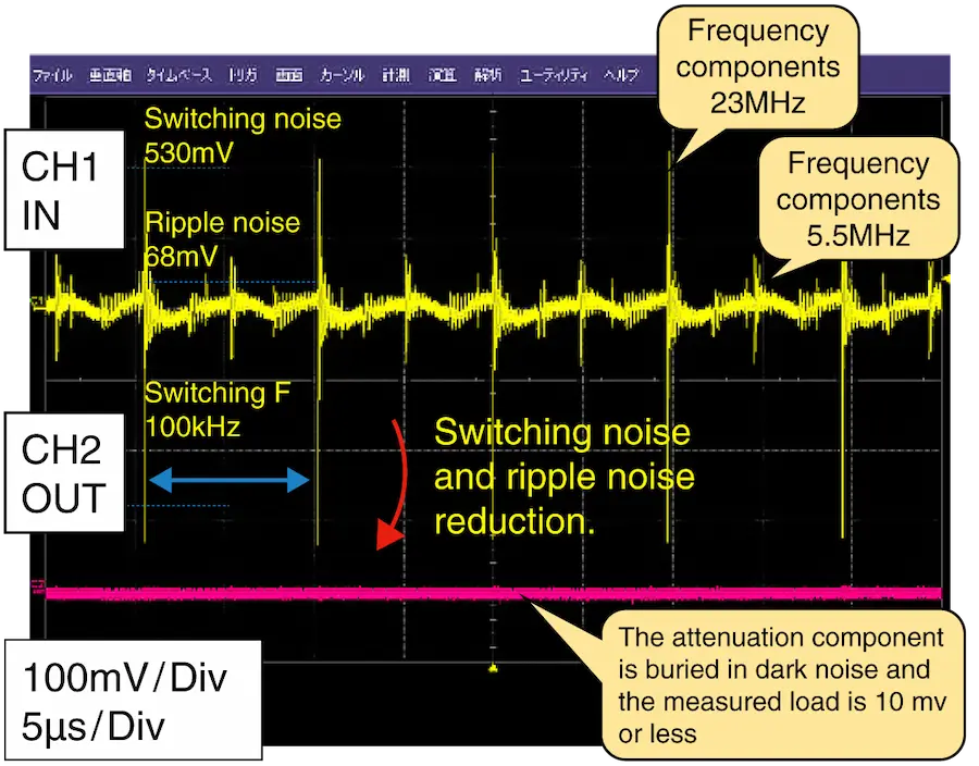
Fig.17 Observation of DC/DC converter noise elimination performance by the SM coil and hybrid capacitor
When inserting an SM coil + hybrid 100μF LCD filter in the DC/DC converter output, at a rated output of 30A, we confirmed that power supply SW noise was attenuated to less than 10mV.
(Remarks:) 10mV is the measurement limit of the oscilloscope.
10. Comparison of 1-turn through structure coil SM series and drum coil
【Overview】
- We compare drum coils and bar coils using a ferrite magnetic material with the same inductance and rated current as the SM series, which uses amorphous magnetic material. This is a comparison with the SM series for conduction noise elimination performance and radiation noise.
- Since drum coils and bar coils have similar characteristics, drum coils are used in this evaluation.
(For coil specifications, see 4. LC filter characteristics and precautions.)
【Conduction noise and radiated noise in this section】
- Conduction noise is noise that propagates through power lines and signal lines.
- In the case of coils, we assume radiation noise to be noise that propagates through open space due to magnetic flux (leakage magnetic flux) radiated into space as a result of the coil arrangement and core structure. This radiation noise magnetically couples with peripheral circuits, generates an induced voltage, and can have adverse effects, including malfunctions.
- This section compares conduction noise elimination performance and radiation noise levels on the AM radio band.
【Coil appearance and structure】
Here, we explain an image of the magnetic flux generated in the core from the core structure of each coil.
| Drum coil (or bar coil) | Our coil SM series |
 |
 |
| (Explanation of structure) The core of the drum coil and bar coil have an open magnetic circuit structure, so the magnetic flux generated in the core becomes a loop that passes through open space. |
(Explanation of structure) Since the core of the SM series has a closed magnetic circuit structure, magnetic flux generated inside the core closes the magnetic flux loop inside the core. This structure makes it difficult for magnetic flux to leak outside the core. |
【Conduction noise removal ability evaluation】
- Filter characteristics
Configure an LC filter for conduction noise removal performance.
To anticipate noise attenuation on the AM radio band, set filter characteristics of roughly -40dB or lower at 500kHz or higher. - Filter input signal
We assume that high voltage spike noise of 50Vpeak/1MHz is input to the filter as conduction noise.
【Radiation noise evaluation method】
We use the following simplified method to validate: (Refer to noise evaluation block diagram)
- Prepare two electrically insulated substrates.
- Set the board on which the LC filter for conduction noise elimination is mounted as the primary board.
- Set the board for checking the influence of radiation noise from the primary board coil as the secondary board.
For the secondary board, install a 1.2V virtual power supply line based on the assumption of, for example, in-vehicle electronic equipment with gradual voltage decline.
Place the secondary board in a position that allows you to sufficiently confirm induced voltage due to radiation noise from the primary board.
In this evaluation, we positioned the board 30mm above the primary board.
【Noise evaluation block diagram】

【Results】
Comparison of conduction noise elimination performance
- Both the SM series and the drum coil have almost the same filter characteristics (conduction noise removal characteristics). (See Fig.18)
Attenuation characteristics are almost as designed, about -40dB or lower at 500kHz or higher.

Fig.18 Comparison of SM coil and drum coil filter characteristics
Presence, absence, influence of radiation noise
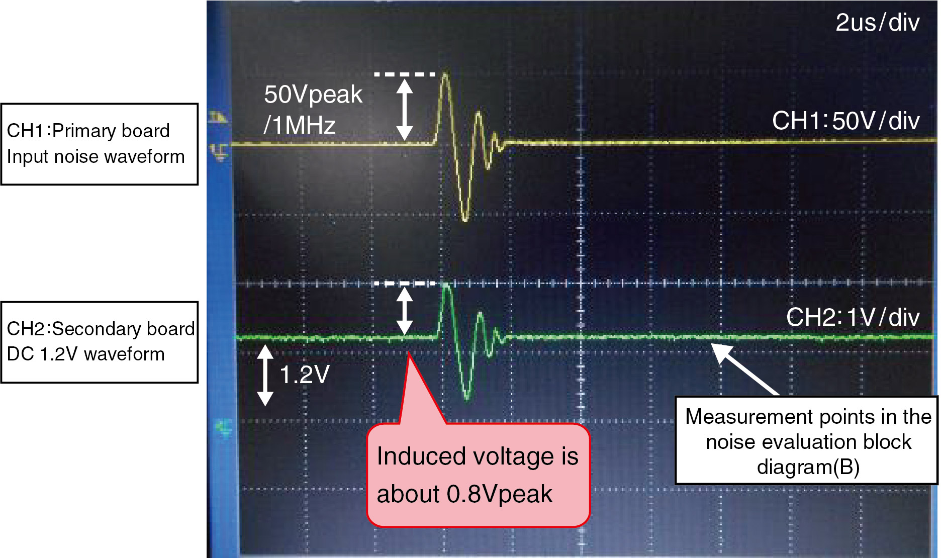
- There are differences between the SM series and drum coils in terms of radiation noise due to magnetic flux leakage. In the coil we evaluated, we confirmed an induced voltage of about 0.8Vpeak. (See Fig.19)
This is roughly 67% of the secondary board virtual power supply line 1.2V, and there are concerns about adverse effects such as malfunction in the actual machine environment. - With SM coils, we confirmed that the induced voltage was within 0.1Vpeak regardless of the layout of the secondary board.
Compared to drum coils and bar coils, this can be expected to greatly reduce concerns about malfunctions in peripheral circuits. (See Fig.20)
| Drum coil | Our coil SM series |
 |
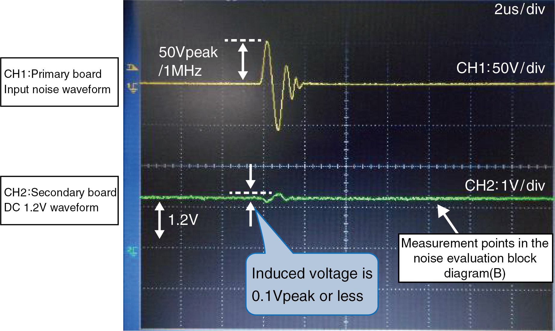 |
| Fig.19 Induced voltage to secondary board due to leakage flux from the drum coil | Fig.20 Induced voltage to secondary board due to leakage flux from the SM series |
【Observations】
- Even if both the SM coil and the drum coil can sufficiently attenuate the conduction noise, the radiation noise due to the magnetic flux is leakage differs significantly.
- Observing the coil structure, the core of the drum coil has an open magnetic circuit structure, resulting in significant magnetic flux leakage. Also, induction voltage (abnormal voltage) due to magnetic coupling with the peripheral circuit becomes very large as radiation noise. Therefore, it is necessary to pay attention to coil placement and peripheral circuit placement.
- On the other hand, since the core of the SM coil has a closed magnetic circuit structure, there is almost no magnetic flux leakage and radiation noise is minor. As such, even if high voltage spike noise is applied, the induced voltage (abnormal voltage) generated in the peripheral circuit will be minor. This allows for flexibility in the placement of coils and the placement of peripheral circuits.
(Supplemental information)
Supplemental information: For the radiation noise in the bottom direction of the coil, making the board a solid pattern creates a magnetic shield, enabling a reduction in the radiation noise in the direction of the bottom of the coil.
If the coil mounting part does not have a solid pattern, it is necessary to consider to the bottom direction of the coil mounting part.
【Summary】
The SM series, a 1-turn penetration structure coil, has less radiation noise due to flux leakage than drum coils and bar coils, even when high voltage spike noise is applied, and can prevent adverse effects such as the malfunction of peripheral circuits.
11. Conclusion
※LC filter using an SM coil and a Hybrid Capacitors
The combined effect of low power loss attributable to the low DCR of the SM coil, the low ESR of the hybrid capacitor, and temperature stability has the following three advantages.
- Can be used for large current power lines.
- Provides attenuation to -40dB/dec.
- Attenuation characteristics do not change with ambient temperatures.
【Supplemental information 1】
When using a hybrid capacitor, steep attenuation characteristics (ideal attenuation) can be obtained, enabling the design of a high cutoff frequency fc.
This can contribute to lower capacitor capacitance and the downsizing of parts.
※LC filter using an SM coil and an Electrolytic Capacitors
On the other hand, aluminum electrolytic capacitors have a high ESR and large temperature fluctuations. However, selection is possible if the following conditions are met.
- Requires a large capacitance.
- Attenuation characteristic to -20dB/dec. possible.
- Temperatures are consistent.
- External size considerations not required.
【Supplemental information 2】
When using an aluminum electrolytic capacitor, the high ESR results in an attenuation characteristic of -20dB/dec. However, by lowering the cutoff frequency fc, it is possible to obtain the attenuation at the target frequency.
※Each capacitor feature summary
(fc: cutoff frequency)
※About SM coils and drum coils
When comparing the conduction noise and radiated noise of the SM series against general drum coils with roughly the same inductance and rated capacity,
even if the SM series coil, whose core has a closed magnetic circuit structure, is subject to extremely high spike noise of several tens of volts,
the radiation noise caused by magnetic flux leakage can be reduced significantly.
As such, it is possible to reduce malfunctions of peripheral circuits.
12. Notes concerning the use of this document
- This document is reference data for the characteristics of the product and does not guarantee the characteristics of the product.
- To ensure correct and safe product use, do not rely on this document and, instead, make judgment after mounting the product and conducting tests.
- This document may be supplemented, revised, or modified without prior notice for improvement or other reasons.
- Please note that Nippon Chemi-Con Corporation will not be held responsible for any damages resulting from the use of this document.
- All copyrights of this document belong to Nippon Chemi-Con Corporation.
- Please refrain from redistributing or reprinting this document.
If you have any questions or inquiries that do not apply to the above, please contact us at the following address.