The FFT analysis function on an oscilloscope is useful when you want to measure the effective value of the ripple current, such as for use in calculating the endurance of an aluminum electrolytic capacitor.
The video below explains the actual process for using this function.
Example of Multiple Overlapping Frequency Components
When using an aluminum electrolytic capacitor in something such as a power factor correction (PFC) circuit, there are overlapping ripple currents ranging from low frequencies from the commercial power supply frequencies (100 Hz or 120 Hz) after rectification and high frequencies coming from the switching terminal.
DC/DC power supplies may also have overlapping ripple currents with multiple switching frequency components and complex frequency components coming from higher harmonics.
In these cases, it is quite difficult to calculate the effective value of the ripple current from the waveform.
FFT analysis
If your oscilloscope has an FFT analysis function, it is possible to calculate the effective value of the ripple current for each frequency. Then you can sum these values to find the effective value of the calculated ripple current for a specific frequency (specific frequency of rated ripple current, such as 120 Hz).
FFT stands for Fast Fourier Transform. When analyzing the frequency and effective value of the ripple current, this operation can be used to decompose the measured waveform into each frequency component and calculate the effective value for each.
Concept of Fourier Transform
Procedure
【Key points for equipment selection】
Oscilloscope
Use a model with a record length of 100k or more.
Current Probes
Make sure to select the proper probe, either an AC probe or a DC probe, depending on the frequency range of the circuit.
Extension cable
If you need to extend the capacitor leads when connecting the current probe, use a thick cable in order to reduce the effect on impedance.
【Oscilloscope operation】
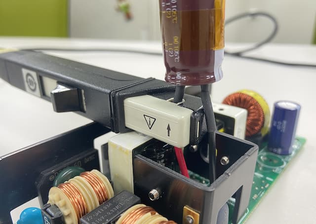
Extend the capacitor terminals with cables and attach the current probe.
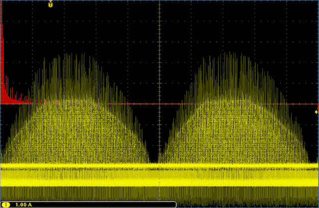
Operate the circuit with the expected load conditions, and get an integral multiple of the waveform period to show on the oscilloscope.
Be aware that the ripple current following FFT transform may not be estimated correctly if it is not an integral multiple of the waveform period.
Example of display showing an integral multiple of waveform period
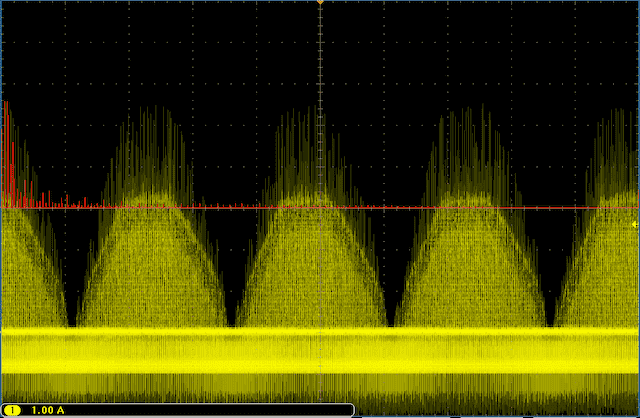
Example of display not showing an integral multiple of waveform period
(The wave is cut off on the left and right)
Use the oscilloscope FFT operation function to switch from time domain display to frequency domain display.
The key point is to display in Linear RMS.
【Processing FFT analysis data】
Export data from the oscilloscope.
You may find it more convenient if you output the data in CSV format.
Open the data in spreadsheet software, and create a scatter plot from the frequencies on the x-axis and effective values of ripple current on the y-axis.
Read the peak value and frequency for the spectrum from the scatter plot.
This value will be the effective value of the ripple current at each frequency.
【Use in calculating capacitor heat generation】
Use the effective value of the ripple current calculated thus far to find the heat generated by the capacitor.
Use the frequency calibration coefficient to convert the effective value of the ripple current at each frequency measured during FFT analysis to the effective value of the ripple current at the rated frequency of the capacitor used (120 Hz or 100 kHz, depending on the series).
Generate the effective values of ripple current after frequency calibration.
Use the rated ripple current and measured values for frequency calibrated ripple current to calculate the value for heat generation.
The method for calculating the heat generation of a capacitor from the measured ripple current value is explained in-depth in our article on "Lifetime of Aluminum Electrolytic Capacitors".
(Ref.) Configuring your oscilloscope
FFT analysis point
With a waveform containing various frequency components, for example, a ripple current waveform containing 120Hz, 80kHz, and 100kHz components, the low frequency components have a greater effect on the internal heat generation of the capacitor than the high frequency components. As such, conduct the FFT on the waveform for integral multiplier cycles of the 120Hz component (lowest frequency component).
(Referencing aluminum electrolytic capacitor impedance frequency characteristics)
The following shows the three methods for gating integral multiplier cycles.
Since the waveform displayed on the screen of the oscilloscope is subject to FFT analysis, adjust the horizontal axis (time axis) of the oscilloscope to display a 120Hz component on the screen and perform FFT with an integral multiplier of the cycle (below described as 120Hz based on the assumption of 60Hz full-wave rectification).
By using the oscilloscope's gating function, the 120Hz component cycle is gated by an integer multiplier, and the FFT is performed on that range.
If finely adjusting the horizontal axis (time axis) or gating does not work, then we recommend capturing waveforms for multiplier cycles (about 10 cycles) on the screen and performing FFT. We recommend setting the time axis to a time range that allows you to judge whether the waveform is continuous at both ends. For a typical oscilloscope, about 10 cycles should be appropriate.
By acquiring waveforms for many cycles, you can reduce the influence of waveform discontinuation at both ends of the screen. However, it should be noted that this is a method to reduce the error, but does not eliminate errors completely.
Oscilloscope window functions
A condition for obtaining accurate FFT analysis results is that the waveform for FFT analysis is repetitive (continuous).
If there is discontinuation in the waveform at both ends of the oscilloscope screen for a periodic waveform, performing an FFT based on that waveform may result in a large error relative to the true value.
Therefore, if there is discontinuation in the waveform at both ends of the screen, a window function is used to convert the discontinuation so that it becomes continuous (weighting is applied to the waveform so that both ends are continuous). There are several types of window functions, but the operator should select the window function based on the purpose and information to be obtained.
Selecting a window function
There are four types of window functions available with a typical oscilloscopes: a rectangular window, a hamming window, a hann window, and a blackman-harris window. We have determined that the rectangular window is optimal for capacitor ripple current.
The reason being that the rectangular window is a window that does not distort the waveform, and is equivalent to no window function. It is also advantageous that it is the window function with the highest resolution since it is not weighted, which would distort the waveform.
The point of caution when performing FFT based on the above content is that only the 120Hz component is the integral multiplier cycle of the repeated waveform. In other words, for other frequency components, there is a discontinuation in the waveform at both ends of the screen.
Specifically, by selecting the rectangular window function, more accurate FFT results can be obtained for the 120Hz component. However, for the FFT results of other frequency components, this results in an error that depends on the degree of waveform discontinuity.
However, since the other frequency components are higher frequency components than the 120Hz component, the effect of III above (reducing the error by capturing waveforms for many cycles) is obtained.
Therefore, we have determined that rectangular window is the optimal window function.
Tags
If you have any questions or inquiries that do not apply to the above, please contact us at the following address.