Surface Treatment Technology for Aluminum Electrode Foils in Aluminum Electrolytic Capacitors
1. Preface
Developments in electronic equipment have been remarkable in recent years. There have been significant advancements in downsizing as well as performance and reliability improvements for active components such as integrated circuits, semiconductor elements, and electron tubes used in the circuits of electronic equipment, passive parts such as L/C/R, and functional and mechanical components.
Among these electronic components, aluminum electrolytic capacitors represent one of the electronic components for which metal surface treatment technology is directly related to their functions. This includes technology such as etching technology designed to increase surface area and anodizing technology used to achieve dielectric film with a high withstand voltage. Unlike surface treatments, which provide decorative and anticorrosive properties, the chemical and electrochemical surface treatments related to these technologies are performed to effectively utilize the electrical properties of the surface treatment film.
Electrolytic capacitors that use an anodized film as a dielectric were originally wet electrolytic capacitors that used an aqueous electrolyte solution. However, at the beginning of this century, the development of a paste-like electrolyte using a combination of ammonium borate and glycerin led to the birth of the so-called dry electrolytic capacitor and the development of a method of making the aluminum anode foil into a cylindrical coil type. This established a foundation for the compact and large-capacity technology for aluminum electrolytic capacitors.
Throughout history, researchers such as Guntherschultze, Betz and many others have made steady progress in basic research on dielectric films for electrolytic capacitors.
In 1956, Western Electric developed a so-called solid electrolytic capacitor that used metal oxide semiconductor manganese dioxide as the electrolyte instead of the above-mentioned pasty electrolyte. More recently, capacitors that use organic semiconductors such as TCNQ as a solid electrolyte have also been put to practical use. Electrolytic capacitors that have been developed as wet or dry over the years are beginning to shift into compact solid electrolytic capacitors.
This process of development is the result of a natural progression of improvements and ingenuity in the performance of electrolytic capacitors in response to the growing demands for downsizing and higher performance for electronic circuits. Recently, circuits have been downsized increasingly to various ICs, LSIs, and ultra-LSIs. As a result, how to mount capacitive elements in these has become an increasingly important issue and demand for chip-type capacitors for surface mounting applications is increasing rapidly.
2. Aluminum Electrolytic Capacitors
An electrolytic capacitor is a capacitor formed by anodizing a metal surface to form a dielectric oxide film. This film is brought into contact with an electrolyte, high-viscosity electrolyte, or solid electrolyte, and electric charge is accumulated between the film and the counter electrode. Metals covered with an oxide film via anodization, known as valve metals, include metals such as aluminum, tantalum, niobium, titanium, hafnium, zirconium, zinc, tungsten, bismuth, and antimony. Of these, aluminum and tantalum are currently used in practical applications for electrolytic capacitors.
Although tantalum is chemically stable and has excellent properties, it is currently not widely used due to its high cost. Aluminum is the most widely used because it is inexpensive and has a wide operating voltage range. The annual growth rate of electrolytic capacitors in terms of global production volume is almost equivalent to the rate of growth for semiconductor parts. It is estimated that the current monthly production volume worldwide has reached approximately 5 billion units.
For a parallel plate capacitor as shown in Figure 1, capacitance (C) is derived using the following formula.
Here, ε is the permittivity of the dielectric, S is the surface area of the dielectric [cm2], and d is the thickness of the dielectric [cm]. In order to obtain a large capacitance (C), the above formula requires a large dielectric constant, a large area, and a thin dielectric.
The ε of aluminum oxide (Al2O3) or tantalum oxide (Ta2O5) films obtained through anodization is 8 to 9 for aluminum and approximately 25 for tantalum. Neither are very large values. However, as described later, anodizing with an appropriate electrolyte yields a very thin film with a high withstand voltage. The surface area can also be increased by etching or using a porous sintered body.
Therefore, aluminum electrolytic capacitors are smaller and less expensive than conventional capacitors, yet have a large capacitance. They are widely used as large-capacity capacitors for their ability to meet recent demand for the downsizing of components.
Figure 2 shows the range of capacitance used for various capacitors commonly used today. In Figure 2, we can see that aluminum electrolytic capacitors cover a large capacitance range.
Figure 3 shows a principle schematic diagram of an aluminum electrolytic capacitor. The thickness (d) of the film achieved through anodization can be adjusted freely by adjusting the operating voltage during anodization.
In other words, aluminum electrolytic capacitors are characterized by a capacity that can be adjusted by changing the anodizing voltage, by the generated film having a property (valve action) that prevents the flow of current in a certain direction (positive direction), and by the fact that it is polar. Furthermore, since the electrolyte is internal, the capacitor itself has film repairability.
The following three points represent the main electrical characteristics required for electrolytic capacitors.
(1) Capacitance and its tolerance
Capacitance at 120Hz is usually expressed in μF, but tolerance is gradually getting smaller, typically ±20% or ±10%.
(2) Leakage current
Although the insulating properties of dielectric films are extremely high, they are not infinite. When a DC voltage is applied, some level of leakage current flows. If this value is large, it affects the performance, endurance, and reliability of the device. Therefore, it should be sufficiently small, and the rate of change is defined.
(3) Series resistance
All capacitors other than ideal theoretical capacitors have an equivalent series resistance. In other words, in an ideal capacitor, while the current leads the potential by 90° phase, actually a lag occurs (this lagging angle is called the dielectric loss angle), producing a current in phase with the voltage. This amount is consumed as electricity inside the capacitor (Figure 4). As a scale for this phenomenon, this is represented by the tangent tanδ of the dielectric loss angle δ, and is referred to as the dielectric dissipation factor. When used in AC circuits, especially at high frequencies, high voltages, and large capacities, this resistance directly affects the amount of heat generated by the capacitor, making it one of the most important electrical characteristics related to endurance.
The usage conditions that affect the electrical characteristics of these capacitors include circuit voltage, ripple current, temperature, frequency, and time. Depending on each condition, the aforementioned electrical characteristics will change considerably. Therefore, the allowed temperature range, voltage (DC, AC), applicable frequency range, etc., will be limited. To obtain more stable performance, the aluminum material, etching conditions, anodizing conditions, electrolyte composition, element structure, and sealing structure are evaluated. Looking at the production of aluminum electrolytic capacitors in terms of surface treatment technology, the following two points are the most important technological fields related to the various electrical characteristics mentioned above.
i) Etching technology for securing a large capacitance per unit area
ii) Anodizing technology for obtaining stable dielectric films


3. Aluminum anodized dielectric coating
The film known as alumite is popular as an anodized film for aluminum. This type of coating makes aluminum relatively soluble in an electrolyte under high electric fields. For example, this is obtained through anodization in an electrolyte such as sulfuric acid, chromic acid, or oxalic acid. This film is porous and can be grown to a thickness of between 10μm and 100μm. It is also used for anti-corrosion and as a coloring film for aluminum sashes.
On the other hand, barrier film is the film formed when aluminum is anodized with a near-neutral electrolyte such as ammonium borate. This barrier film is extremely thin and dense, with a thickness of 1μm or less, and has a high dielectric strength voltage of 106 to 107 V/cm. Since it blocks current well, it is also called an insulating film and is used as a dielectric film for electrolytic capacitors.
The dielectric film used in electrolytic capacitors is an extremely thin and dense barrier film, whether it is Ta2O5 for tantalum or Al2O3 for aluminum. In such a high electric field, the relationship between the ion current (i) flowing in the film and the electric field strength (E) is derived via equation (1), which assumes that Guntherschultze and Betz follow the exponential law.
Here, A=A'exp(-W/kT) and B=B'/kT, including the temperature dependence of the ion current (i). This formula (1) conforms to both the Cabrera-Mott theoretical formula derived on the assumption that the metal-oxide interface is rate-limiting, and the Verway theoretical formula derived on the premise that the oxide interior is rate-limiting. Since they match, this can be viewed as having a theoretical basis.
With a growth rate of the film under constant current, the rate of increase in film thickness is expressed by equation (2).
D: thickness of the film
t: time
i: ion current density
Z: molecular weight
M: Faraday number required to produce 1g molecular weight of the oxide
ρ: density of the film
The differential electric field strength Ed (=dV/dD) varies only slightly with increasing oxide film thickness under a constant ion current density. Assuming this to be constant, the speed of increase in potential is given by formula (3).
That is, the growth rate is proportional to the ion current. Also, since the strength of the electric field in the film does not change, the voltage rises linearly with time when anodization is carried out at constant current density. On the other hand, looking at film growth under constant voltage, Ed decreases as the film grows under constant voltage, so the ionic current also decreases. As the reduction speed for the electric field decreases, the current reduction speed also decreases. Thus, the speed of growth becomes so slow that in practice the film thickness reaches a certain limit, hence the expression Å/V.
It is worth noting that, if anodization is continued endlessly at a constant current, according to equation (3), the bath voltage will rise infinitely. However, in reality, there is a limit. Once the voltage reaches a certain voltage value, which depends on the anode metal, type of chemical solution, solution concentration, current density, etc., the voltage no longer rises no matter how long the chemical conversion continues. This is because film formation by ionic conduction shifts to film insulation breakdown due to electronic conduction, and normal film formation is no longer performed. In fact, before reaching this maximum breakdown voltage, the rate of film formation slows down, sparks are generated from the anode surface, and eventually the breakdown voltage is reached (Figure 5). The voltage that generates this spark is called the spark voltage, and this spark voltage is sometimes measured and used as a test method to determine the quality of the anode material. The voltage range that can be anodized is about 800V for aluminum foil and about 400V for tantalum foil.
Now, the thickness of the anodized film is proportional to the anodizing voltage, while the capacitance is inversely proportional to the thickness of the dielectric film. With the surface area for foil or the weight for powder, (Capacitance C) × (Formation voltage V) ≈ constant relationship is approximately established.

4. Manufacturing method of aluminum electrode foil and aluminum electrolytic capacitor
Depending on the type of anode body, there are aluminum and tantalum electrolytic capacitors. Depending on the shape of the anode body, there are foil and sintered type. They can be classified into solid-state types using oxide semiconductors, etc. Here, we will introduce the manufacturing method of aluminum dry electrolytic capacitors using a typical aluminum foil, focusing on the surface treatment of the aluminum electrode foil.
Figure 6 shows an example of the manufacturing process for an aluminum electrolytic capacitor.
(1) Aluminum foil
The aluminum foil used as the anode is a rolled product with a width of 500mm and a thickness of 0.05 to 0.1mm. The purity of aluminum is about 4N (99.99%), and main impurities are silicon, iron, copper, magnesium, and zinc. Depending on the application, either soft or hard aluminum is used (specified below). The type and amount of impurities have a large effect on the type and magnification of etch pits in the etching process, and also on the leakage current of the anodized film, which has a large effect on the endurance of the product. Aluminum foil of about 2N is normally used for the cathode. Figure 7 shows an example of the etching process.
(2) Pretreatment
For the purpose of degreasing the foil or removing the natural oxide film, pretreatment is performed to homogenize the surface condition. Common methods include trichlorethylene degreasing, warm or cold alkali cleaning, mineral acid treatment, alternating current or cathodic electrolysis cleaning, and thorough water washing after completion.
(3) Etching
It is a process that enlarges the surface of the aluminum foil in order to obtain as large a surface area as possible in the same area, and is extremely important as it is directly related to capacity. There are also chemical methods, but electrochemical etching is commonly used in terms of magnification and ease of management. Aqueous chloride solutions such as hydrochloric acid and salt are mainly used for the etching bath, and the power source is direct current, alternating current, alternate use or superimposition. The dominant reaction is shown by the following equation in the case of an aqueous chloride solution.
Al+3Cl-→AlCl3+3e-
Factors that affect magnification are temperature, bath concentration, pH, current density, amount of electricity, and electrode structure. If the magnification is different in the width direction and the length direction of the foil, the capacity will vary when the foil is cut to a fixed length for capacitor elements after the anodization process performed after this etching process. The most important control item is to prevent variations in magnification in the width and length directions.
By the way, in anodization performed after etching, the thickness of the anodized film generated varies depending on the level of the anodization voltage (usually in the range of 5V to 700V). Therefore, it is necessary to control the etching type according to the anodizing voltage. As in Figure 8, (A) is the etched state, (B) the surface after low pressure formation, and (C) the same surface after high pressure formation. In (C), even if the surface area is increased through etching, the effect is ignored and the capacity cannot be extracted to a large extent. Therefore, relatively large holes must be drilled to account for high pressure.
For this reason, it is common to conduct the etching process based on two etching conditions, one for high pressure and one for low pressure, or three for high pressure, medium pressure, and low pressure, depending on the magnitude of the anodizing voltage during subsequent anodizing treatment.
For low pressure applications, hard foils are used for direct current etching, or hard or soft foils are used for alternating current etching, in order to obtain fine etching holes. Due to the difference in etching mechanism, fine tunnel pits grow in DC etching, while fine cubic pits grow in AC etching.
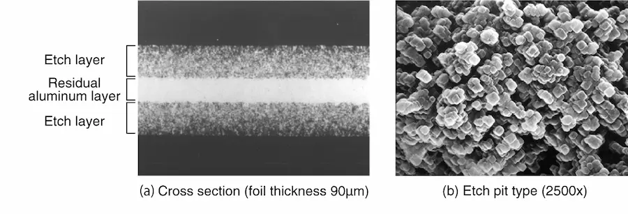
In AC etching, the etching progresses uniformly from both sides of the foil in the depth direction, so the residual aluminum core is maintained uniformly and the strength of the foil can be kept high (Photo 1). Since the foil width used in small aluminum electrolytic capacitors for low voltage is extremely narrow, such a high-strength AC etching foil is mainly used.
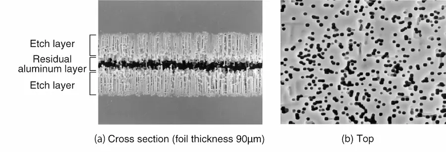
On the other hand, for high-pressure applications, a soft foil with aligned crystal orientation is used for DC etching, and tunnel pits with large diameters are aligned and etched in the depth direction (Photo 2). The samples in Photos 1 and 2 were both anodized after etching, and only the underlying aluminum was dissolved away without dissolving the oxide film, clearly indicating the etching layer and the etching pit type.
After the etching process, the foil surface is purified and treated with nitric acid to remove powdery aluminum generated during electrolysis as well as chlorine ions generated during etching and impurities appearing on the surface before thoroughly washed with pure water. After drying, it is rolled. In particular, chlorine ions are contaminants that must be absolutely avoided in order to ensure long endurance and high reliability for aluminum electrolytic capacitors. Therefore, it is necessary to wash thoroughly via a shower, ultrasonic cleaning, etc. The surface of the etched aluminum foil is active, so extreme care must be taken when storing the foil. In this way, the magnification of the etched foil (compared to the surface area of the original foil) reaches approximately 100 times for low pressure and approximately 20 times for high pressure.
(4) Anodization
In the process of forming the oxide film that will be the dielectric of the capacitor, the rolled aluminum foil that has been etched in the previous process to expand its surface area is used as the anode, and is anodized continuously. Figure 9 is an example of a continuous anodization process.
A buffer solution such as ammonium borate, ammonium phosphate, or organic acid ammonia is used as the electrolyte, and anodization is performed at a voltage of 140 to 160% of the capacitor rated voltage (usually 6.3V to 500V). There is a one-step method and a multi-step method. The former is when the anodizing voltage is around 100V or less. With high-voltage anodization, the anodizing voltage is increased sequentially in two or three steps. When performing high-pressure anodization, a method of boiling in pure water before anodization is usually used to form a pseudo-boehmite film (AlOOH) on the outermost surface. This has advantages such as obtaining a crystalline film with high withstand voltage, reducing power consumption, and increasing processing speed (Photo 3, Photo 4). The anodized foil is washed with water, dried, and wound up after its leakage current is sufficiently reduced.
After finishing the anodizing process, the foils are inspected for capacity per unit area, cut to the required size, attached with leads, and rolled up by inserting separator paper between the opposing cathode foils to create the coil element. The separator paper serves to prevent mechanical contact between the anode foil and the cathode foil, as well as impregnate and retain the electrolyte.
(5) Electrolyte impregnation
The coil element is impregnated with electrolyte. For the electrolyte, a polyhydric alcohol such as ethylene glycol, glycerin, etc., is used as the main solvent, into which an electrolyte such as ammonium borate or organic acid ammonium salt that does not penetrate aluminum is dissolved. The electrolyte is formulated to have film repairability and appropriate resistance, and is a paste at room temperature. The composition of this electrolyte is an important item to consider because it greatly affects the temperature characteristics, frequency characteristics, product life, etc., the three major electrical characteristics required of the capacitor.
The viscosity of this electrolyte is lowered to a high temperature of 100 to 130°C, and the wound element is vacuum impregnated or dip impregnated so that the surfaces of both electrode foils are completely covered with the electrolyte. The impregnated element is enclosed in an aluminum case and becomes a finished product. For the purpose of forming a film on the cut surface during cutting and repairing cracks in the film caused by mechanical strain during winding, the finished product is aged again by applying voltage at a high temperature to sufficiently reduce the leakage current. This becomes the finished product as an aluminum electrolytic capacitor.


5. Electron micrographs of various aluminum electrode foils
If you have any questions or inquiries that do not apply to the above, please contact us at the following address.