Using the lifetime estimation tool
This document explains how to use the lifetime estimation for aluminum electrolytic capacitors.
Selecting the desired product
- Selecting from a parts number page
The parts number is input automatically when you transition to the lifetime estimation.
Move on to usage condition settings. - Selecting based on the type or series
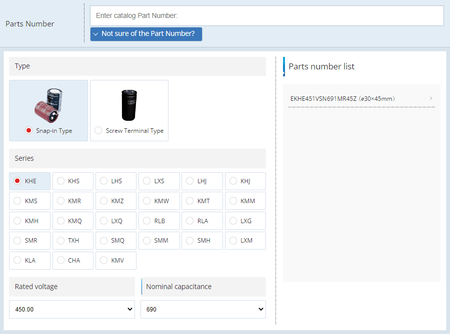
Click on “Not sure of the Part Number?” to select the type of the part you plan to use.
Series names are displayed so select the desired series.
Selecting the rated voltage and nominal capacitance displays parts numbers on the right side of the screen (at the bottom if using a smartphone).
Find and select the same size as the product you plan to use.
Setting usage conditions
- Inputting the Bank Type
Here, input the number of series and parallel connections for aluminum electrolytic capacitors you will connect to the applicable circuit.
Bank Type example:(Caution) For series connections, we recommend using a balancing resistor to evenly distribute voltage between capacitors.


Series: 1 Parallel: 1 Series: 2 Parallel: 1 Series: 1 Parallel: 3 Series: 3 Parallel: 4
- Inputting the life profile
Input the usage conditions for the capacitors.
You can set multiple conditions if environmental conditions will change during the period of use.
Environmental conditions may fluctuate due to the following types of factors.
■When use will change due to a mixture of high and low-load times or a suspension of operations
■Seasonal changes in ambient temperature
■When there are both time-based and seasonal factors
- Ambient temperature
This is the temperature near the capacitor.
If the capacitor is installed as an internal component of a chassis or other structure, capacitor temperature may be higher than the external temperature due to ambient heat from peripheral components.
The surrounding temperature set here should be a temperature that accounts for ambient heat.
(E.g.: External temp. of 25°C, ambient heat of 18°C → surrounding temperature of 43°C)
Furthermore, there is no need to include temperature increases due to self-heating of the capacitor.
- Operating Voltage
Input the voltage to be applied overall on the circuits you set for Bank Type.
E.g.: When applying 1100V on a circuit of three products with a rated voltage of 400V connected in a series, input the operating voltage as 1100V.
- Ripple current
Input the ripple current flowing to the overall circuit set in Bank Type.
E.g.: Input the ripple current as 8Arms if 8Arms will flow into a circuit comprised of parallel connection of four capacitors.
Typically, the ripple current flowing into capacitors is superimposed by components of the low frequency (50 to 300Hz) originating from the commercial power source and the high-frequency originating from the switching element (several kHz or more).
Use FFT analysis or other means to separate the ripple current frequency component and then input the ripple current effective value for each frequency.
- Life ratio
For multiple usage conditions, input the time-based percentage at which each condition is triggered.
Configure settings so that the total life ratio for all conditions equals 100%.
To input multiple usage conditions, press to add a life profile input column.
- Calculation results
The lifetime estimation results are displayed as hours and years.
The lifetime estimation is calculated up to a maximum of 15 years (131,400 hours). Changing usage conditions will not cause the displayed results to change if the calculation results exceed 15 years (131,400 hours).
Input Restrictions
An error will be displayed, and the estimated lifetime cannot be calculated under the following conditions:- Ambient Temperature:
Do not enter a temperature that exceeds the maximum allowable temperature for the product category. - Operating Voltage:
Do not enter a voltage that exceeds the rated voltage.
For multiple components connected in series, an error will occur if the divided voltage across any component exceeds its rated voltage. - Series Connection:
Products that use conductive polymer technology are not compatible with series connections. - Ripple Current:
Each product has a specified maximum allowable ripple current, which varies depending on the ambient temperature.
Do not enter a ripple current that exceeds this limit. - Life Ratio:
An error will occur if the total life ratio for all conditions does not equal 100%.
If you have any questions or inquiries that do not apply to the above, please contact us at the following address.