How to use capacitor model data in LTspice
Contents
SPICE model data for our products is distributed as component data for LTspice, which was created by Analog Devices.
The method indicated on this page allows you to use SPICE model data without the need to download data from our website.
For certain products, you may experience a time lag between distribution start and publication to LTspice. In such cases, please download the data from the website for use.
For certain products, you may experience a time lag between distribution start and publication to LTspice. In such cases, please download the data from the website for use.
Model data selection procedure
This article explains the procedures using a sample semiconductor circuit (LTC7800) as an example.Even if using a different semiconductor or a circuit you created, you can use the same procedure to switch to the applicable capacitor.
- Refreshing LTspice data
Please refresh the LTspice component data prior to creating the circuit. You can refresh data by selecting [Sync Release] under [Tools] in the menu bar.
Our models are not included in the old component data. - Creating a new circuit
Here, we are using a sample semiconductor circuit (LTC7800).
First, open the [Create New Circuit] window.
Click on the area circled in red in Figure 1.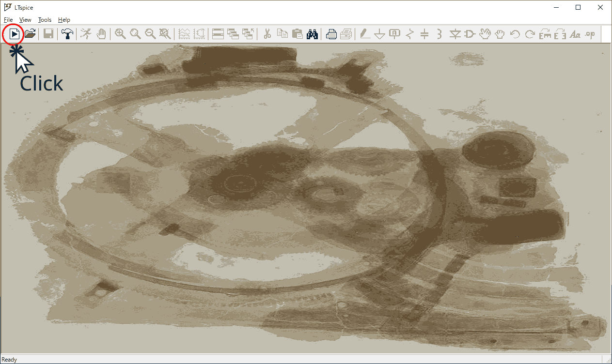
Fig.1 Circuit creation window in LTspice
- Selecting the sample circuit
Click the area circled red from the parts at the top of the window in Figure 2. You can select Component from this icon.
In the red square part of the window that opens, enter [LTC7800], which is the name of the semiconductor we will use as an example.
If a matching part is found, it will be selected automatically from the list at the bottom.
Make sure that [LTC7800] is selected, then click [Open this macromodel's example circuit] to load the circuit data.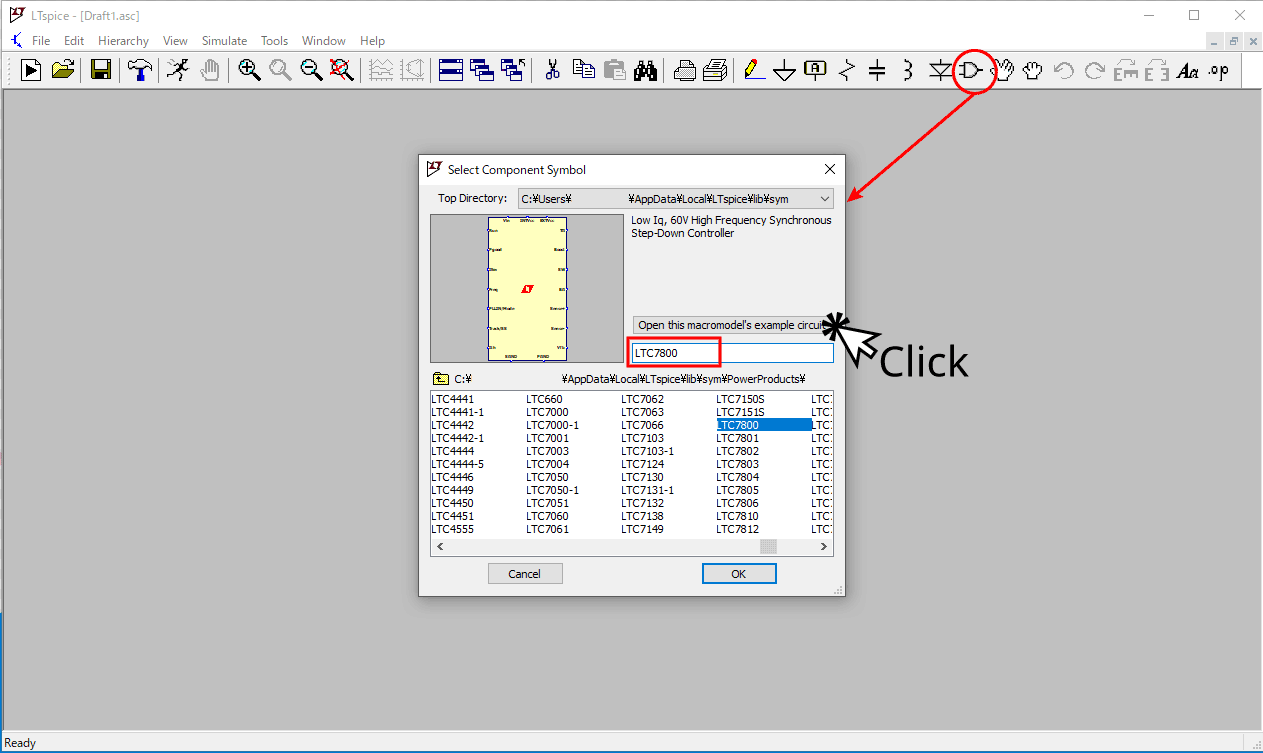
Fig.2 Sample circuit selection window
- Replacing the component for evaluation
Replace the component arranged on the sample circuit.
Here, we will replace the output smoothing capacitor with a hybrid aluminum electrolytic capacitor.
First, click the scissors icon in the red circle in the area labeled STEP1 in Figure 3, and then click on the component you want to delete.
Here, we indicate [Delete] on the component to be deleted.
Then, click the Component icon in the red circle in the area labeled STEP2 in Figure 3.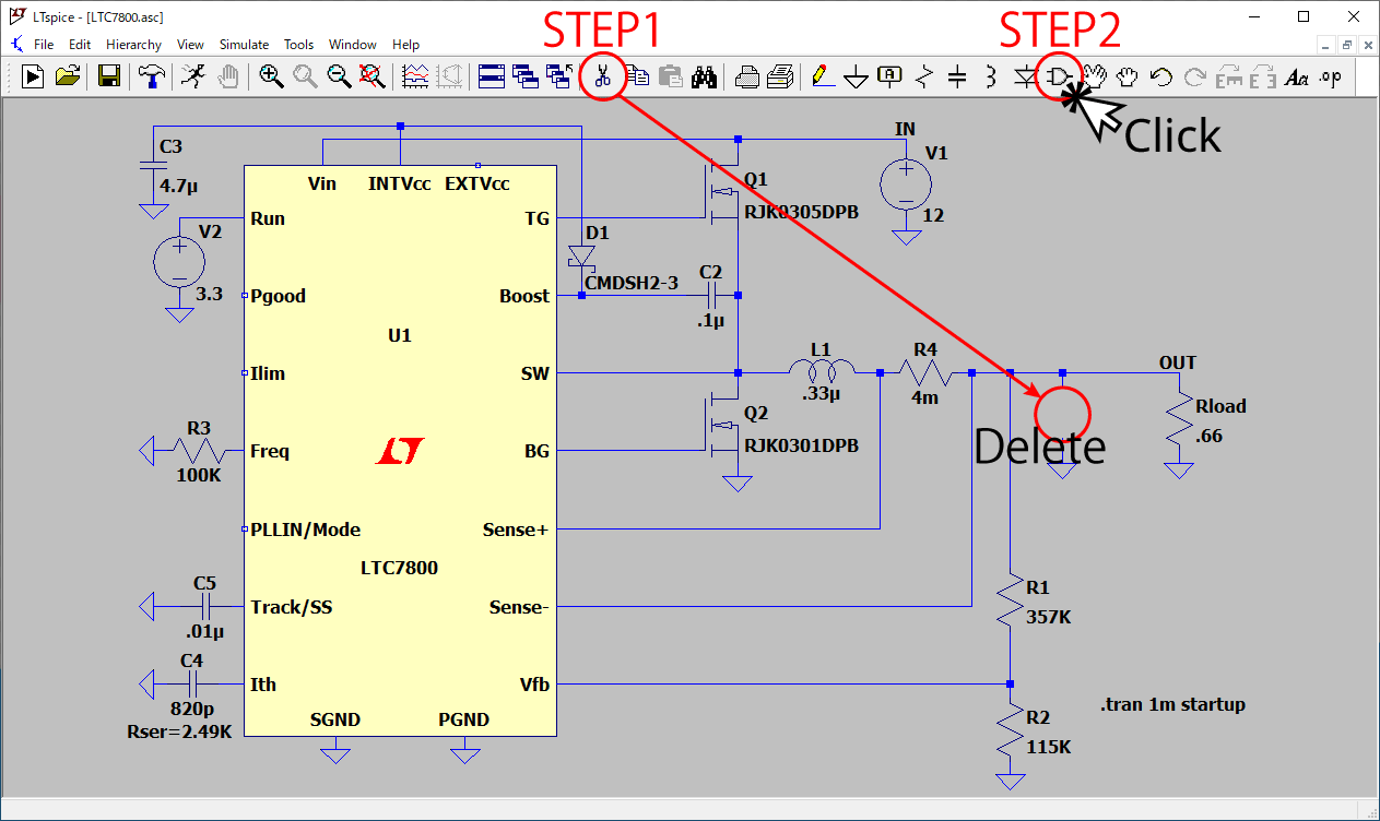
Fig.3 Deleting a circuit component and about the Component icon
- Selecting a Nippon Chemi-Con product
Clicking the Component icon shown in Figure 3 above will open the window shown in Figure 4 below.
First, click on the item indicated with [Contrib], then click on the item indicated as [CHEMI-CON].
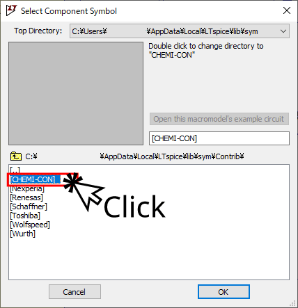
Fig.4 Product data storage location
- Selecting an item to use
Selecting [CHEMI-CON] in Figure 4 above displays options such as [Capacitors] and [Inductors].
Here, select [Capacitors] and then select [Alcap-PolymerHybrid-SMD], which contains data on surface mount-type hybrid aluminum electrolytic capacitors. This displays a list of included products.
The product categories included in each folder are shown in the table.In this example, select [HHXC250ARA101MF80G] and click the [OK] button. (Figure 5)Product Type Folder Conductive Polymer Aluminum Solid Capacitors - SMD Alcap-PolymerSolid-SMD Conductive Polymer Aluminum Solid Capacitors - Radial Lead Type Alcap-PolymerSolid-THD Conductive Polymer Hybrid Aluminum Electrolytic Capacitors - SMD Alcap-PolymerHybrid-SMD Conductive Polymer Hybrid Aluminum Electrolytic Capacitors - Radial Lead Type Alcap-PolymerHybrid-THD Aluminum Electrolytic Capacitors - SMD Alcap-SMD Aluminum Electrolytic Capacitors - Radial Lead Type Alcap-THD 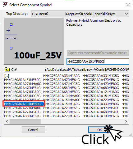
Fig.5 Selecting an item part number
- Arranging on the circuit
You are now holding [HHXC250ARA101MF80G]. Place it in the section where you deleted the output smoothing capacitor earlier. It will be mounted when you click on the corresponding part marked [Click to Insert] as shown in Figure 6.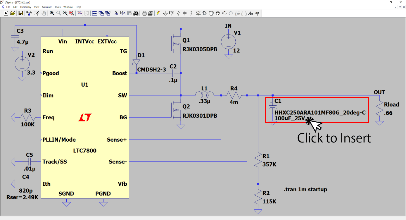
Fig.6 Component placement
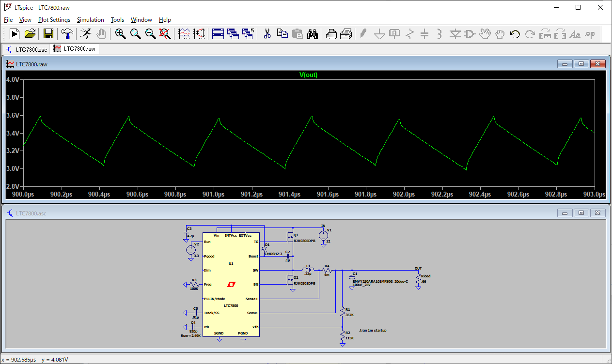
- Running the simulation
You can now run the simulation. Click [Run] at the top to run the simulation.
How to simulate characteristics by ambient temperature
Characteristics of aluminum electrolytic capacitors that use an electrolyte fluid, such as ESR and capacitance, change significantly depending on the ambient temperature.In the SPICE model data distributed by our Company, we provide model data by temperature for products that use an electrolyte fluid.*1
*1 Excludes certain items
- Temperature data selection window
Align the pointer with the target electrolytic capacitor and right-click.
In Figure 7, this is indicated in red as STEP1.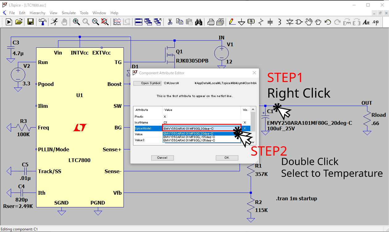
Fig.7 Temperature data switch window
- Selecting data
In the displayed window (Figure 7), click the Value area of the item labeled [Attribute "SpiceModel"] to display selectable temperature data. (Step 2 is written in red.)● Category minimum temperature● +20℃● Category maximum temperatureTypically, products are set with these three parameters.
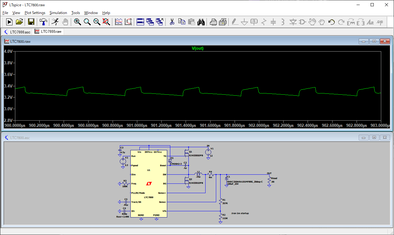
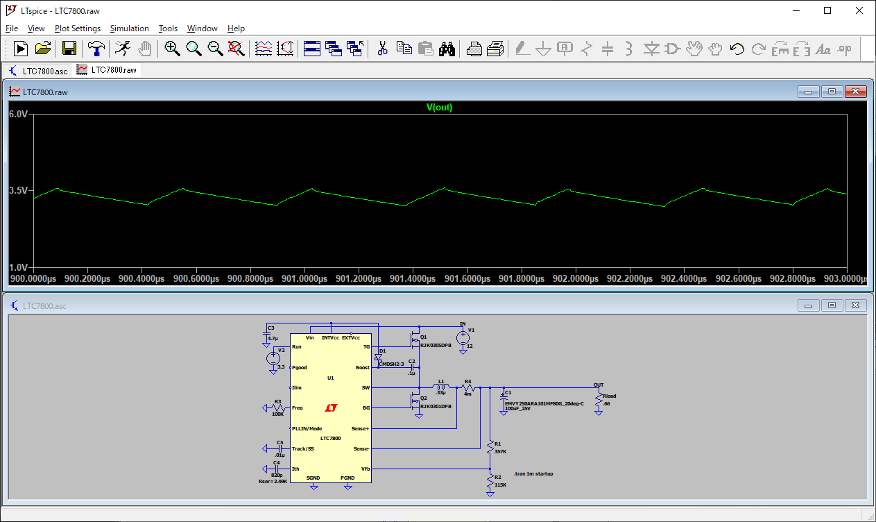
Simulation results by aluminum electrolytic capacitor type
Here, we will compare hybrid aluminum electrolytic capacitors and aluminum electrolytic capacitors that use an electrolyte fluid.Although the products have the same capacitance, they have different ESR values, and it can be seen that the output ripple voltages are significantly different.
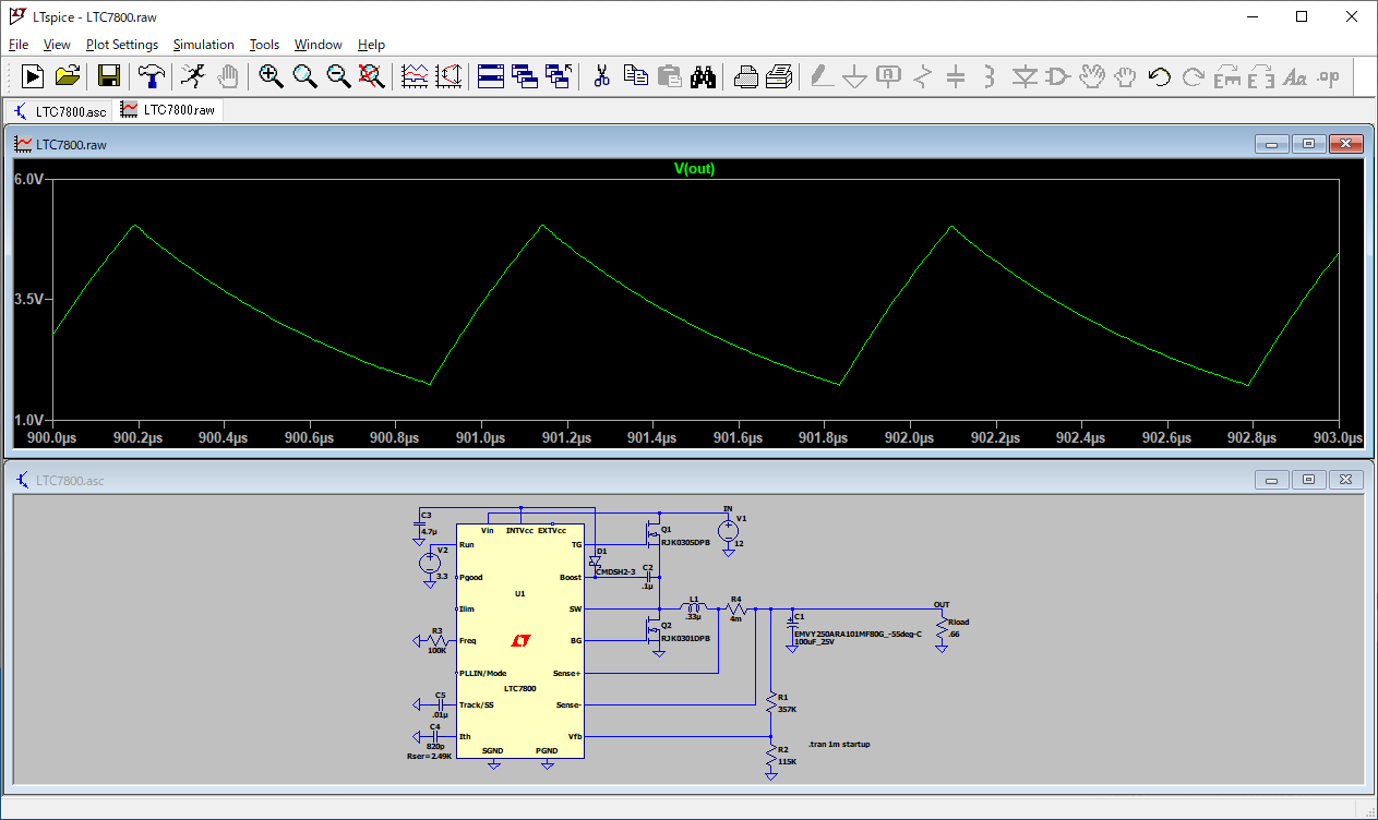
Simulation results when switching temperature data
Next is the result of switching temperature data using an aluminum electrolytic capacitor that uses an electrolyte fluid.Under low temperature (-55℃) conditions, ESR increases significantly and capacitance decreases. As a result, it can be seen that the output ripple voltage has increased significantly.
Caution
SPICE simulates the circuit operations mathematically but operations may differ from the actual prototype. As such, please use the tool as a reference only.Our Company shall bear no liability whatsoever for any malfunctions that occur.
If you have any questions or inquiries that do not apply to the above, please contact us at the following address.