Structure of Aluminum Electrolytic Capacitor
1. Basic Model of Aluminum Electrolytic Capacitors
Capacitors are passive components. Among the various kinds of capacitors, aluminum electrolytic capacitors offer larger CV product per case size and lower cost than the others. In principles of capacitor, its fundamental model is shown in Fig. 1 and its capacitance (C) is expressed by Equation (1) below:
【Fig.1】Basic model of capacitor
- ε
- : Dielectric constant
- S
- : Surface area of dielectric [m2]
- d
- : Thickness of dielectric [m]
However, by extending the surface area (S) of the aluminum foil electrode by means of etching, and by electrochemically forming a thinner but highly voltage-withstandable layer of oxide layer dielectric, the aluminum electrolytic capacitor can offer a larger CV product per case size than other types of capacitors. A basic model of aluminum electrolytic capacitor is shown in Fig.2 .
- Anode
- …Aluminum foil
- Dielectric
- …Electrochemically formed oxide layer (Al2O3) on the anode
- Cathode
- …A true cathode is electrolytic solution (electrolyte).

- CA、CC
- : Capacitance due to anode and cathodes foils
- DA、DC
- : Diode effects due to oxide layer on anode and cathode foils
- LA、LC
- : Inductance due to anode and cathode terminals
- R
- : Resistance of electrolyte and separator
- RA、RC
- : Internal resistance of oxide layer on anode and cathode foils
2. Structure of Aluminum Electrolytic Capacitor
The aluminum electrolytic capacitor has, as shown in Fig.3 , a roll of anode foil, paper separator, cathode foil and electrode terminals (internal and external terminals) with the electrolyte impregnated, which is sealed in an aluminum can case with a sealing material. The terminal draw-out structure, sealing material and structure differ depending on the type of the capacitor. Fig.4 shows typical examples.
【Fig.3】Basic model of element
 |
 |
 |
| Surface Mount Type | Radial Lead Type | Snap-in Type |
3. Features of Capacitor Materials
Aluminum, which is main material in an aluminum electrolytic capacitor, forms an oxide layer (Al2O3) on its surface when the aluminum is set as anode and charged with electricity in electrolyte. The aluminum foil with an oxide layer formed thereon, as shown in Fig.5 , is capable of rectifying electriccurrent in electrolyte. Such a metal is called a valve metal.
【Fig.5】V-I characteristics of aluminum oxide
<Anode aluminum foil>
First, the foil material is electromechanically etched in a chloride solution to extend the surface area of the foil. Secondly, for the foil to form an aluminum oxide layer (Al2O3) as a dielectric, more than the rated voltage is applied to the foil in a solution such as ammonium borate. This dielectric layer is as dense and thin as 1.1 to 1.5 nm/volt and showing a high insulation resistance (108 - 109 Ω/m).
The thickness of the oxide layer determines the withstand voltage according to their direct proportional relationship. For the etching pits to be shaped to the intended thickness of the oxide layer, the pit patterns have been designed to have efficient surface area extension depending on the intended withstand voltage (see Fig.6)
| Low Voltage Foil | High Voltage Foil |
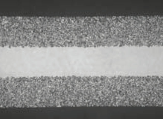 |
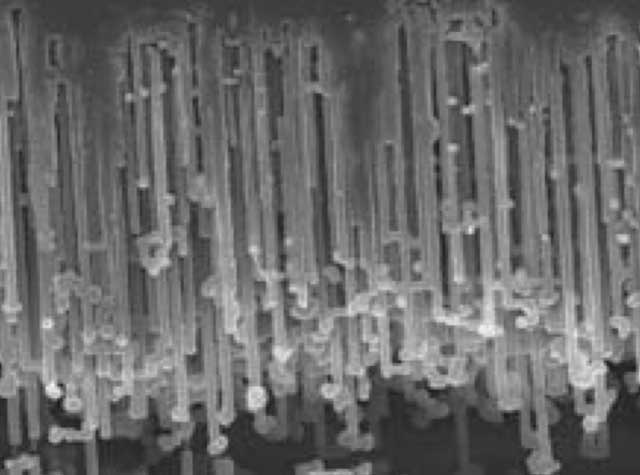 |
| (Fracture surface of AC etched foil) | (Fracture surface of DC etched foil) Replica |
【Fig.6】Cross section of aluminum etched foil(SEM)
<Cathode aluminum foil>
An etching process is performed to the cathode aluminum foil as well as the anode foil. However, the formation process for oxide layer is generally not performed. Therefore, the surface of the cathode foil only has an oxide layer (Al2O3) that has spontaneously formed, which gives a withstand voltage of about 0.5 volt
<Electrolyte>
The electrolyte, an ion-conductive liquid functions as a true cathode coming into contact with the dielectric layer on the surface of the anode foil. The cathode foil serves as a collector electrode to connect the true cathode with the external circuit. Electrolyte is an essential material that controls the performance of the capacitor (temperature characteristics, frequency characteristics, service life, etc.).
<Paper separator >
The separator maintains uniform distribution of the electrolyte and keeps the anode-to-cathode foil distance unchanged.
<Can case and sealing materials>
An aluminum can case and seal materials mainly consisting of rubber are used for the purpose of keeping airtightness.
If you have any questions or inquiries that do not apply to the above, please contact us at the following address.