Aluminum Electrolytic Capacitors for Through Hole Reflow ECST250E222M20X1MA
- RoHS2
- For Through Hole Reflow
- For All Reflow
- Machine Inserting
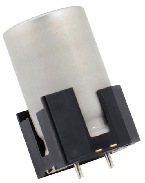
Possible completed reflow procedure due to adopting Aluminum Electrolytic Capacitor of lead type which is possible to make reflow.
Eliminating flow steps reduces the work involved in process and facility management, contributing to total cost improvements.
Improves terminal position accuracy to enable automated mounting. Possible to tuning in a high sound quality.
| Part Number | ECST250E222M20X1MA |
|---|---|
| Status | In Production |
| Polarity | Polar |
| Category Temperature Range | -40℃~105℃ |
| Rated Voltage | 25 Vdc |
| Capacitance | 2200 µF |
| Capacitance Tolerance | -20~20%(M) / 20℃, 120Hz |
| Dimensions ⌀ D | 12.5mm |
| Dimensions L | 23mm max |
| Rated Ripple Current | 2000mArms / 105℃ / 100kHz |
| Leakage Current | 1650 μA max / 20℃, after 1 minute |
| Dissipation Factor (tanδ) | 0.16 max / 20℃, 120Hz |
| Endurance Temperature / Time / Overload | 105℃ / 3000hrs / DC+Ripple |
| Vibration Resistance | 10 to 200 to 10Hz in about 1minute, 98m/s2 (10G), 2hours in each for X and Y and Z axis |
Reference Weight
|
4.6g |
| Minimum Order Quantity | 300pcs |
RoHS Compliant
|
Compliant |
Rated Ripple Current Multipliers
拡大表示する
| Frequency [Hz] | 120 | 1k | 10k | 100k |
|---|---|---|---|---|
| Multipliers | 0.60 | 0.87 | 0.95 | 1.00 |
Dimension [mm]
![Dimension [mm]](/products/module/images/ECST250E222M20X1MA_1.svg)
Recommended soldering conditons
-
- Peak Temperature
- 240℃
- Time maintained above 230℃
- 20sec
- Preheat
- 150~180℃, 120sec
- Reflow number
- 2 times or less
-

Notes on Reflow soldering
Reflow the capacitors within recommended reflow soldering conditions.
Verify there is no temperature stress to the capacitors because the following differences might degrade capacitors electrically and mechanically.
Please consult us if other reflow conditions are employed.
1. Location of components : Temperature increases at the edge of PC board more than the center.
2. Population of PC board : The lower the component population is, the more temperature rises.
3. Material of PC board : A ceramic made board needs more heat than a glass epoxy made board. The heat increase may cause damage to the capacitors.
4. Thickness of PC board : A thicker board needs more heat than a thinner board. The heat increase may damage the capacitors.
5. Size of PC board : A larger board needs more heat than a smaller board. The heat increase may damage the capacitors.
6. Solder thickness : If very thin cream solder paste is to be used for SMD types, please consult with us.
7. Location of infrared ray lamps : IR reflow as well as hot plate reflow heats only on the reverse side of the PC board to lessen heat stress to the capacitors.
8. Please consult us about vapor phase soldering (VPS).